a cardan-type u-joint may require what tool(s) to replace
A universal joint
A universal joint (also chosen a universal coupling or U-joint) is a joint or coupling connecting rigid shafts whose axes are inclined to each other. It is commonly used in shafts that transmit rotary movement. It consists of a pair of hinges located close together, oriented at 90° to each other, connected past a cross shaft. The universal joint is not a constant-velocity joint.[1]
U-joints are likewise sometimes called by various eponymous names, as follows:
- Cardan joint, afterwards Gerolamo Cardano, a polymath of the 16th century who contributed to cognition of various clever mechanisms, including gimbals
- Hooke joint or Hooke'due south joint, after Robert Hooke, a polymath of the 17th century who contributed to knowledge of various clever mechanisms
- Spicer articulation, afterward Clarence Westward. Spicer and the Spicer Manufacturing Company, who manufactured U joints
- Hardy Spicer joint, after the Hardy Spicer brand, a successor to the Spicer make
History [edit]
This video shows dissimilar parts and operation of the universal shaft.

Spicer universal joints for motor cars, 1916.
The chief concept of the universal joint is based on the design of gimbals, which have been in use since antiquity. One apprehension of the universal joint was its apply by the ancient Greeks on ballistae.[2] In Europe the universal articulation is frequently called the Cardano articulation (and a drive shaft that uses the joints, a Cardan shaft), subsequently the Italian mathematician Gerolamo Cardano, who was an early writer on gimbals, although his writings mentioned but gimbal mountings, not universal joints.[3]
The mechanism was subsequently described in Technica curiosa sive mirabilia artis (1664) by Gaspar Schott, who mistakenly claimed that it was a abiding-velocity joint.[four] [5] [6] Before long later, between 1667 and 1675, Robert Hooke analysed the joint and found that its speed of rotation was nonuniform, merely that this property could be used to rails the movement of the shadow on the face of a sundial.[iv] In fact, the component of the equation of time which accounts for the tilt of the equatorial plane relative to the ecliptic is entirely analogous to the mathematical description of the universal joint. The first recorded utilise of the term universal articulation for this device was by Hooke in 1676, in his book Helioscopes.[7] [8] [ix] He published a description in 1678,[ten] resulting in the use of the term Hooke'southward joint in the English language-speaking world. In 1683, Hooke proposed a solution to the nonuniform rotary speed of the universal joint: a pair of Hooke'due south joints ninety° out of phase at either end of an intermediate shaft, an organisation that is now known equally a type of abiding-velocity joint.[4] [11] Christopher Polhem of Sweden later re-invented the universal joint, giving rise to the proper name Polhemsknut ("Polhem knot") in Swedish.
In 1841, the English scientist Robert Willis analyzed the motion of the universal joint.[12] Past 1845, the French engineer and mathematician Jean-Victor Poncelet had analyzed the movement of the universal joint using spherical trigonometry.[13]
The term universal joint was used in the 18th century[10] and was in common use in the 19th century. Edmund Morewood's 1844 patent for a metal blanket machine called for a universal joint, past that name, to accommodate small alignment errors between the engine and rolling mill shafts.[14] Ephriam Shay's locomotive patent of 1881, for example, used double universal joints in the locomotive'south drive shaft.[15] Charles Amidon used a much smaller universal articulation in his bit-caryatid patented 1884.[16] Beauchamp Tower's spherical, rotary, high speed steam engine used an adaptation of the universal joint circa 1885.[17]
The term Cardan joint appears to be a latecomer to the English language. Many early on uses in the 19th century announced in translations from French or are strongly influenced by French usage. Examples include an 1868 report on the Exposition Universelle of 1867[18] and an commodity on the dynamometer translated from French in 1881.[xix]
In the 20th century, Clarence W. Spicer and the Spicer Manufacturing Visitor, as well equally the Hardy Spicer successor brand, helped further popularize universal joints in the automotive, farm equipment, heavy equipment, and industrial machinery industries.
Equation of motion [edit]

Diagram of variables for the universal joint. Axle 1 is perpendicular to the red plane and axle 2 is perpendicular to the blue plane at all times. These planes are at an bending β with respect to each other. The athwart displacement (rotational position) of each axle is given past and respectively, which are the angles of the unit vectors and with respect to their initial positions forth the x and y axis. The and vectors are fixed by the gimbal connecting the 2 axles and then are constrained to remain perpendicular to each other at all times.


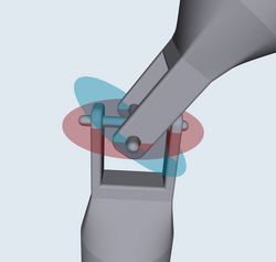
A sample universal joint colour-coded to the diagrams nearly the equation of movement. The red and blue planes are visible.

Angular (rotational) output shaft speed versus rotation angle for dissimilar bend angles of the articulation


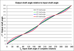
Output shaft rotation angle, versus input shaft rotation bending for different bend angles of the joint

The Cardan joint suffers from one major problem: even when the input drive shaft axle rotates at a constant speed, the output drive shaft axle rotates at a variable speed, thus causing vibration and wear. The variation in the speed of the driven shaft depends on the configuration of the joint, which is specified by iii variables:
- the bending of rotation for axle 1
- the angle of rotation for axle 2
- the bend angle of the joint, or angle of the axles with respect to each other, with zip being parallel or straight through.

These variables are illustrated in the diagram on the right. Also shown are a fix of fixed coordinate axes with unit of measurement vectors and and the planes of rotation of each beam. These planes of rotation are perpendicular to the axes of rotation and practice not motility as the axles rotate. The two axles are joined by a gimbal which is not shown. All the same, beam ane attaches to the gimbal at the blood-red points on the ruby plane of rotation in the diagram, and axle 2 attaches at the bluish points on the blue aeroplane. Coordinate systems stock-still with respect to the rotating axles are defined as having their x-axis unit vectors ( and ) pointing from the origin towards one of the connexion points. As shown in the diagram, is at angle with respect to its beginning position along the x axis and is at angle with respect to its beginning position along the y axis.


is bars to the "red plane" in the diagram and is related to by:
![{\displaystyle {\hat {\mathbf {x} }}_{1}=\left[\cos \gamma _{1}\,,\,\sin \gamma _{1}\,,\,0\right]}](https://wikimedia.org/api/rest_v1/media/math/render/svg/29b84fdcd5b6bc07d771b025df6ccac73e27c185)
is bars to the "blueish aeroplane" in the diagram and is the outcome of the unit vector on the x axis being rotated through Euler angles ]:
![{\displaystyle {\hat {x}}=[1,0,0]}](https://wikimedia.org/api/rest_v1/media/math/render/svg/0bd3be5ddf79743233234f9f2af9943acc1aa0a7)

![{\displaystyle {\hat {\mathbf {x} }}_{2}=[-\cos \beta \sin \gamma _{2}\,,\,\cos \gamma _{2}\,,\,\sin \beta \sin \gamma _{2}]}](https://wikimedia.org/api/rest_v1/media/math/render/svg/e880dc9a98c0dd932d775f23b8bee4642451847d)
A constraint on the and vectors is that since they are stock-still in the gimbal, they must remain at right angles to each other. This is and so when their dot product equals zero:

Thus the equation of motion relating the two angular positions is given by:

with a formal solution for :
![{\displaystyle \gamma _{2}=\tan ^{-1}\left[{\frac {\tan \gamma _{1}}{\cos \beta }}\right]\,}](https://wikimedia.org/api/rest_v1/media/math/render/svg/4efd57686906137bb9839377919de9311799d024)
The solution for is not unique since the arctangent function is multivalued, however it is required that the solution for be continuous over the angles of interest. For example, the post-obit explicit solution using the atan2(y, x) function will exist valid for :


The angles and in a rotating joint volition be functions of time. Differentiating the equation of motion with respect to fourth dimension and using the equation of motility itself to eliminate a variable yields the relationship betwixt the athwart velocities and :


As shown in the plots, the angular velocities are not linearly related, but rather are periodic with a menstruation one-half that of the rotating shafts. The angular velocity equation can again be differentiated to become the relation between the angular accelerations and :


Double Cardan shaft [edit]
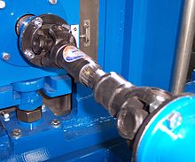
Universal joints in a driveshaft
A configuration known as a double Cardan joint drive shaft partially overcomes the problem of jerky rotation. This configuration uses ii U-joints joined past an intermediate shaft, with the 2nd U-joint phased in relation to the first U-articulation to cancel the changing athwart velocity. In this configuration, the angular velocity of the driven shaft volition match that of the driving shaft, provided that both the driving shaft and the driven shaft are at equal angles with respect to the intermediate shaft (merely not necessarily in the same plane) and that the two universal joints are 90 degrees out of stage. This assembly is ordinarily employed in rear bicycle drive vehicles, where information technology is known every bit a drive shaft or propeller (prop) shaft.
Fifty-fifty when the driving and driven shafts are at equal angles with respect to the intermediate shaft, if these angles are greater than zero, oscillating moments are practical to the iii shafts every bit they rotate. These tend to bend them in a direction perpendicular to the common plane of the shafts. This applies forces to the support bearings and can cause "launch shudder" in rear wheel drive vehicles.[xx] The intermediate shaft volition also have a sinusoidal component to its angular velocity, which contributes to vibration and stresses.
Mathematically, this can be shown as follows: If and are the angles for the input and output of the universal joint connecting the drive and the intermediate shafts respectively, and and are the angles for the input and output of the universal joint connecting the intermediate and the output shafts respectively, and each pair are at angle with respect to each other, then:


If the 2d universal joint is rotated xc degrees with respect to the first, and so . Using the fact that yields:


and it is seen that the output drive is only ninety degrees out of phase with the input shaft, yielding a constant-velocity drive.
NOTE: The reference for measuring angles of input and output shafts of universal joint are mutually perpendicular axes. Then, in absolute sense the forks of the intermediate shaft are parallel to each other. (Since, one fork is interim as input and the other fork is interim as output for shafts and above ninety degree phase departure is mentioned between the forks.)
Double Cardan joint [edit]
A double Cardan joint consists of two universal joints mounted back to back with a centre yoke; the heart yoke replaces the intermediate shaft. Provided that the angle betwixt the input shaft and centre yoke is equal to the bending betwixt the centre yoke and the output shaft, the second Cardan joint volition cancel the velocity errors introduced past the first Cardan joint and the aligned double Cardan joint will human action every bit a CV joint.
Thompson coupling [edit]
A Thompson coupling is a refined version of the double Cardan joint. Information technology offers slightly increased efficiency with the penalty of keen increase in complication.
See also [edit]
- Canfield joint
- Constant-velocity joint
- Elastic coupling
- Gear coupling
- Hotchkiss bulldoze
- Rag joint
- Twin Spring Coupling joint
Notes [edit]
- ^ UjjwalRane (8 July 2010). "Kinematics with MicroStation - Ch02 J Hookes Joint". Archived from the original on 11 March 2016. Retrieved iv May 2018 – via YouTube.
- ^ see: "Universal Joint - Invented by Gerolamo Cardano" "Archived copy". Archived from the original on 2017-04-22. Retrieved 2017-04-21 .
{{cite web}}: CS1 maint: archived copy as title (link) - ^ See:
- Tony Rothman (2013) "Cardano v. Tartaglia: The Smashing Feud Goes Supernatural," p. 25. Available on-line at: Arxiv.org. (Annotation that Rothman mentions Wikipedia's error regarding Cardano'southward supposed invention of the universal joint.)
- Hans-Christoph Seherr-Thoss, Friedrich Schmelz, Erich Aucktor, Universal Joints and Driveshafts: Analysis, Blueprint, Applications (Berlin, Germany: Springer Verlag, 1992), p. i.
- Marie Boas, The Scientific Renaissance: 1450-1630 (New York, New York: Harper Brothers, 1962), p. 186 Archived 2016-04-11 at the Wayback Auto.
- James Eckman, Jerome Cardan (Baltimore, Maryland: The Johns Hopkins Press, 1946.), p. 77.
- Hieronymi Cardanime (Gerolamo Cardano), De Subtilitate Libri XXI. (On subtle things in 21 books) (Basel, Switzerland: Sebastian Henric Petri, 1553), Liber XVII. De Artibus, Artificiosisque; rebus. (Book 17. On crafts and ingenious devices), p. 817. (Note: (1) This book is a reprint of the 1500 original. (2) In the margin of p. 817 is printed: Sedes mira (miraculous chair).) From p. 817: Archived 2017-10-11 at the Wayback Machine "Simili ratione inventũ est, ut Cæsaris sedes ita disponeretur, ut quocumque situ constituatur, ille immobilis, ac commodè dum vehitur sedeat. Hoc tractum ex armillarum ratione: cum enim circuli tres chalybei constituentur, polis sursum, deorsum, antè, retro, dextra ac sinistra mobilibus, cum plures non possint esse situs, necesse est ipsum in essedo quomodocumque agatur quiescere perpetuò." (By similar reasoning, [it] has been establish that the Emperor's chair might be so arranged that he [remain] fixed in whatever orientation be decided and he sit comfortably while he is transported. This is based on the logic of the gimbal mounting: the three steel rings are arranged past the movable poles [i.east., ends of the axes] up, downwardly, forward, backwards, right and left, when more [motions] cannot exist allowed, [because information technology] is necessary [that] he in the railroad vehicle somehow exist fabricated to remain yet constantly.)
- Hieronymi Cardani (Gerolamo Cardano), Mediolanensis Philosophi ac Medici Celeberrimi Operum [Of the very famous works of the Milanese philosopher and physician] (Lyon (Lugdunum), France: Jean Antoine Huguetan and Marc Antoine Ravaud, 1663), vol. 10: Opuscula miscellanea (Miscellaneous works), Paralipomenon (Supplement), Liber 5. De rebus factis raris & artificiis (Book 5. On rare and ingeniously fabricated things), Caput Vii. De Armillarum instrumento (Chapter seven. On the armillary), pp. 488-489.
- ^ a b c Mills, Allan, "Robert Hooke's 'universal articulation' and its awarding to sundials and the sundial-clock", Notes & Records of the Royal Order, 2007, accessed online Archived 2015-09-25 at the Wayback Car 2010-06-sixteen
- ^ Gasparis Schotti, Technica Curiosa, sive Mirabilia Artis, Libris XII. … [Curious works of skill, or marvelous works of craftsmanship] (Nuremberg (Norimberga), (Deutschland): Johannes Andreas Endter & Wolfgang Endter, 1664), Liber IX. Mirabilia Chronometrica, … (Book ix. Marvelous Clocks, … ), Caput V. Signa chronometrica optica, seu indices. (Chapter 5. Marvelous visual clocks, or clocks with hands), pp. 664-665: Propositio Twenty. Indicem sinuosum & obliquatum per anfractus quosvis, sine Rotis dentatis quocumque lubet educere. (Suggestion 20. [How], without any gears, to lead the twisting, turning pointer [i.e., the shaft that drives the clock's hands] through whatever curve 1 pleases.) In the margin is printed: Vide Iconism. VII. Fig. 32. (Run into Plate vii, Figure 32.), which depicts Schott's universal joint. Schott offset notes that there may be occasions when a clock's gear works and its face can't be conveniently aligned; e.g., public clocks installed in towers. He then mentions, in the description of its structure (Technasma, the Greek give-and-take for "artifice"), that the universal joint resembles a gimbal that is used to hold an oil lamp so that information technology won't spill oil. Schott's joint consists of ii forks (fuscinula), each of which consists of a shaft to which a metal strip, bent into a semicircle, is fastened to one finish. Almost each end of the semicircle, a pigsty is drilled. A cantankerous with four perpendicular artillery (crux sive 4 brachia) is also made. The holes in each semicircle fit over the ends of an opposing pair of arms. The angle betwixt the shafts must be greater than a right angle. In discussing the joint's movement (Motus), Schott claims that the 2 shafts move at the same speed (i.due east., they form a constant-velocity articulation): " … horum autem ductum necesse est sequatur & altera fuscinula, parique cum priore illa feratur velocitate: unde si fuerit unius fuscinulae motus regularis circularis, erit similis & alterius … " ( … but this driven [fork] must follow the other [driving] fork, and information technology be born at a speed equal to the former: whence if i fork's movement were regularly circular, it will be similarly with the other … ).
- ^ For a (partial) history of universal joints, see: Robert Willis, Principles of Machinery … , 2d ed. (London, England: Longmans, Light-green, and Co., 1870), Part the 5th: On Universal Joints, pp. 437-457.
- ^ "universal, a. (adv.) and n.", para.thirteen, Oxford English Dictionary Online, accessed 2010-06-16
- ^ Hooke first described a universal joint in Hevelius' instrument in: Robert Hooke, Animadversions on the first part of the Machina Coelestis … (London, England: John Martyn, 1674), p. 73. Hither he calls the joint a "universal Instrument". From page 73: I shall testify " … what use I have made of this Joynt, for a universal Instrument for Dialling, for equalling of Time, for making the Manus of a Clock move in the Shadow of a Fashion, and for performing a multitude of other Mechanical Operations." The joint is depicted on Plate X, Fig.due south 22 and 23, which are available at: Posner Memorial Collection - Carnegie Mellon University Archived 2015-11-17 at the Wayback Machine
- ^ Robert Hooke, A Description of Helioscopes, and Some Other Instruments (London, England: John Martyn, 1676), p. 14. From p. fourteen: "The Universal Joynt for all these manner of Operations, having not had time to describe the terminal Exercise, I shall now more particularly explain." Illustrations of Hooke's universal joint appear on p. forty, Fig.s 9 and 10; available at: ETU Library ; Zurich, Switzerland Archived 2015-09-23 at the Wayback Machine.
- ^ a b Review of Ferdinand Berthoud's Treatise on Marine Clocks, Appendix Art. VIII, The Monthly Review or Literary Journal, Vol. L, 1774; meet footnote, page 565.
- ^ Gunther, Robert Theodore, Early on Scientific discipline in Oxford, vol. vii: "Life and piece of work of Robert Hooke, Part II" (Oxford, England: Dawsons of Pall Mall, 1930), pp. 621–622.
- ^ Willis, Robert, Principles of Mechanisms, … (London, England: John Due west. Parker, 1841), pp. 272-284.
- ^ J. V. Poncelet, Traité de mécanique appliquée aux machines, Function one (Liége, France: Librairie scientifique et industrielle, 1845), pp. 121-124.
- ^ Edmund P. Morewood, Improvement in Coating Iron and Copper, U.South. Patent 3,746, Sept. 17, 1844.
- ^ Ephraim Shay, Locomotive-Engine, U.Due south. Patent 242,992, June 14, 1881.
- ^ Charles H. Amidon, Bit-Brace, U.S. Patent 298,542, May 13, 1884.
- ^ Douglas Cocky. "The Tower Spherical Engine".
- ^ William P. Blake, Report of the Commissioner to the Paris Exposition, 1867, Chapter 1, Transactions of the California State Agricultural Order, During the Years 1866 and 1867, Vol X, Gelwicks, Sacramento, 1868.
- ^ The Dynamometer Residual, [Van Nostrand'southward Engineering Magazine], Vol. XXV, No. CLVI (Dec. 1881); folio 471.
- ^ Electronically-controlled adjustable meridian bearing support subclass - US Patent 6345680 Archived February v, 2009, at the Wayback Machine
References [edit]
- Theory of Machines iii from National University of Ireland
External links [edit]
- [1] by Sándor Kabai, Wolfram Demonstrations Project.
- DIY: Replacing Universal Joints at Nearly.com.
- Thompson Couplings Limited explanation of the Thompson coupling.
- Universal Joint Failure - Custom Solutions Accost Common Problems
- Universal Joint Phasing - The Concept and Importance of Bulldoze Shaft Phasing and Alignment
- The Thompson Coupling - invented past Glenn Thompson by ABC Television (The New Inventors, broadcast Feb 2007).
- U.S. Patent 7,144,326 (constant-velocity coupling).
- About universal joints at McMaster Carr.
- Cardan Shaft at McMaster Carr.
Source: https://en.wikipedia.org/wiki/Universal_joint
Belum ada Komentar untuk "a cardan-type u-joint may require what tool(s) to replace"
Posting Komentar